Grant Part #4503 - Standard Installation Kit Manuel d'utilisateur
Naviguer en ligne ou télécharger Manuel d'utilisateur pour Équipement pour l'eau Grant Part #4503 - Standard Installation Kit. Grant Part #4503 - Standard Installation Kit User Manual Manuel d'utilisatio
- Page / 2
- Table des matières
- MARQUE LIVRES
Résumé du contenu
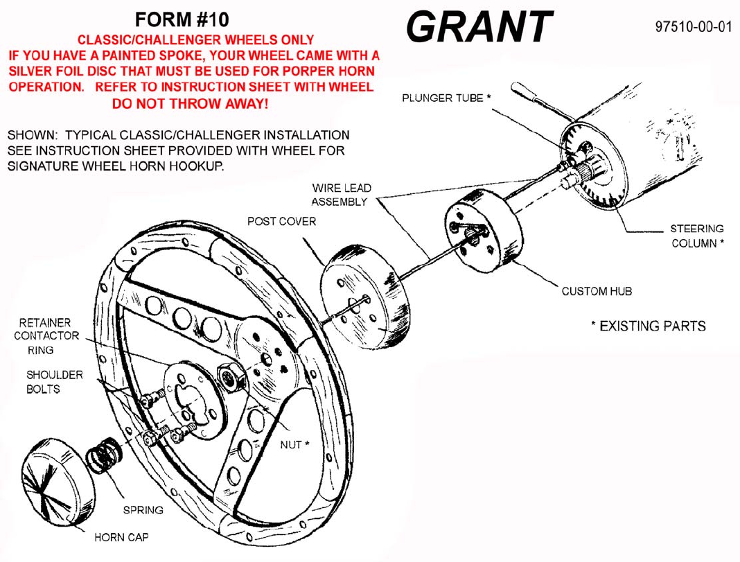
1. Point wheels straight ahead and disconnect battery or pull horn fuse before starting removal of the old wheel so ho
Our Limited Warranty We warrant this product for ninety (90) days from the date of
Produits connexes et manuels pour Équipement pour l'eau Grant Part #4503 - Standard Installation Kit
 (1 pages)
© 2020, manymanuals.fr. Tous droits réservés | 0.685 s |
 Manymanuals.com
 Manymanuals.de
 Manymanuals.fr
 Manymanuals.it
 Manymanuals.pl
 Manymanuals.cz
 Manymanuals.es
 Manymanuals-pt.com
Commentaires sur ces manuels